12v 7ah Battery Charger Circuit Diagram Pdf
- 12v 7ah Battery Charger Circuit Diagram Pdf Download
- 12v Battery Charger Circuit Board
- 12v 7ah Sla Battery Charger
- 12v 7ah Battery Charger Circuit Diagram Pdf Schematic
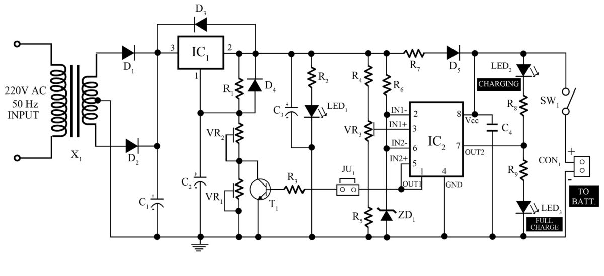
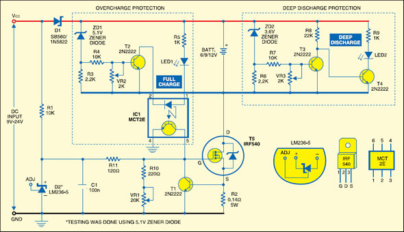
In this DIY Project, I will show you how to build a simple Lead Acid Battery Charger Circuit using easily available components. This circuit can be used to charge Rechargeable 12V Lead Acid Batteries with a rating in the range of 1Ah to 7Ah. AUTOMATIC BATTERY CHARGER Abstract In this study, charger is designed for 12V sealed lead-acid batteries. The designed device consists of a circuit which performs charging, a circuit displaying battery charge level during or resting state of charging (may change according to requirements), a circuit controlling. Simple automatic cut off battery charger. Comes to look in the circuit. I use it for 12V 7AH battery and lower. So the charging current is 2A. So I use a 2A, 12V transformer in the unregulated power supply. In load or while in charge is 13V to 15VDC. Suppose, the voltage battery is 12.4V. The relay does not work. MANUAL BATTERY CHARGER FOR 12 VOLT. Mobile Phone Battery Charger Circuit Diagram 12V Battery Charger Circuit Diagram for Gel Cells in fast Charging Solar Battery Charger Circuit Diagram Pdf. This 50a battery charger circuit diagram will contain an overall description of the Format: PDF SIMPLE CIRCUIT DIAGRAM OF 12V BATTERY CHARGER.
12 volt 1.3AH battery charger circuit diagram, Battery charge for 12 volt 1.3 Ampere hour battery has been designed using L200 and with over voltage protection circuit. In this article, I am going to tell you about very useful battery charge circuit diagram. L200 voltage regulator is used for control voltage purpose. Optocoupler is used for feedback to control voltage appearing across battery by turn on and off L200 voltage regulator.
Battery charger have enormous applications from domestic use to industrial use. Battery charge as it name suggests is used to charge battery. Battery charger used in UPS battery charger , car battery charger, solar battery charger and many other enormous applications. In this article I am discussing 12 volt 1.3AH battery charger.
12 volt battery charger circuit diagram :
Circuit diagram of battery charger is given below. In this circuit diagram LED is used as a voltage indicator to show charging. When battery is charging, LED will glow. Otherwise it will remain off.
In above circuit diagram 220 volt to 24 volt step down transformer is used to step down voltage 24 volt AC. After that 4A rectifier is used to rectify voltage from AC to pulsating DC. you can used any 4A rectifier or can used 4A diode connected in full bridge configuration. After that 1000uF capacitor is used to remove ripples from pulsating DC. This contant DC voltage is fed to input of L200 voltage regulator.
L200 is linear voltage regulator which can supply contant 2A from voltage range of 3 volt to 36 volt. L200 voltage regulator can provide variable voltage with ability to change the output voltage according to reference voltage. Check L200 data sheet to know more about it and its use in various configurations.
TLP251-1 optocoupler is used for feedback to change refrence voltage according to battert voltage. As battery voltage rises TLP251-1 decrease the voltage at the output of L200 by changing the value of reference voltage. Diode 1N4007 is used to limit output current to 700mA, Because 700mA current is safe to charge 1.3AH battery.
In upcoming articles, I will post article on 12 volt 7AH battery charger circuit diagram. For more information keep visiting our website. Kindly don’t forget to share it with your friends and on social media. That’s what you can do for us in return. Thanks 🙂
Simple 12 volt battery charger circuit diagram designed by using few easily available components, and this circuit is suitable for different types of batteries needs 12 Volt. You can use this circuit to charge 12V SLA battery or 12V Gel cell battery and so on. This circuit is designed to provide charging current upto 3 amps and this circuit don’t have reverse polarity protection or over current protection so kindly test this circuit before stepping into battery charging.
This Simple 12 volt Battery Charger Circuit Diagram gives you a outline design for the general battery charger and you can add additional features to this circuit like reverse polarity protection by placing a diode at the output. (Diode anode to output positive supply and diode cathode as output positive terminal) and over current protection setup using transistors. The following charger circuit just a Raw prototype to give 12 Volt output to battery.
Circuit Diagram
Components Required
- Step down transformer (0-14V AC / 3 Amps) – Choose depends on your requirements.
- Bridge Rectifier module BR1010
- Capacitors 0.01µF, 100µF/25V each one
- Resistor 1KΩ (Use 0.25W for normal LED)
- LED
Construction & Working
Use Required ampere Step down transformer for your target battery, here we have used 0-14V AC / 3 Amps Step down transformer and for AC to DC rectification we have used Bridge Rectifier module BR1010 which gives High efficient DC supply with high Current rating.
12v 7ah Battery Charger Circuit Diagram Pdf Download


BR1010
12v Battery Charger Circuit Board
This Bridge Rectifier module will have four terminals, two for AC supply input noted with sign wave and two terminals for DC output noted with positive and negative sign.
12v 7ah Sla Battery Charger
C1 and C2 capacitors are performing as filter in this circuit then LED indicates the presence of DC power supply at the output. Connect the target Battery at the output to get charged.


